Hello everyone! Welcome to Arduino Geek. Today we will discuss about an Arduino based Self balancing robot. So let's get started. Self balancing robot is an example of Arduino project. A balancing robot comes under the category of autonomous project, where the robot tries to balance itself by using the gyroscope sensor MPU 6050. It is quite popular and difficult from the other arduino project. Balancing robot can be made in many ways and in many forms also. Even you can use a normal dc motor or a good quality stepper motor. That is totally depends upon you. According to my suggestion you will get a better performance in stepper motors. In this blog we are going to discuss each and everything about a self balancing robot using stepper motor. We also connect the balancing robot with our smart phone using Bluetooth. And I will tell you, how to control this robot from our smart phone using EZ Gui application.

Lots of developer are facing different problems while making a self balancing robot. In this session I tell you all the necessary steps, which you have to do for building a self balancing robot. Also I will discuss about the common mistakes that are usually made by the developers while building a balancing robot. And if you follow all the steps without any mistake, your robot will be working.
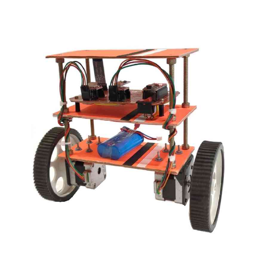
Components –
- NEMA 17 Stepper Motor
- Arduino Nano
- A4988 Motor Driver
- MPU 6050
- HC-05 Bluetooth Module
- 12 Volt Lipo Battery
- 100uF Capacitor
- 1KOHM Resistor
- Wheels
- Nuts & Bolts
Structure –
For a balancing robot the most important thing is the frame. The performance of the balancing robot is totally dependent on the structure of the frame. Try to make the frame small and as light as possible. A light weighted frame will help to get an optimal performance. The basic approach is to make a three layer frame, where the motors are connected at the bottom layer and the remaining circuit will be fixed in the middle layer. However you can also customize the design according to the project requirement.

Here we are going to follow the basic approach, which is a three layer frame. You have to put all the heavy equipment (like motors and battery) at the bottom layer. Then you need to put the circuit in the middle layer. Do not put anything on top layer. It may affect the performance of robot. Also check the alignment of the frame. The alignment should be perfect without any fault.
Circuit Connection –
Now you have to make the circuit. You can make the circuit at your home by using vero board or you can directly order a PCB from any PCB manufacturing company. While designing the circuit, you have to keep some important fact in your mind. Try to put the gyroscope sensor mpu 6050 at the middle of the circuit. Also place the a4988 motor driver at any side of the circuit. It is recommended to use Arduino Nano in spite of using Arduino Uno. This will make the circuit simple and less bulky. Now take a look at the connection below –

MPU 6050 Connection –
- SDA – A4 of Arduino
- SCL – A5 of Arduino
A4988 Motor Driver Connection –
(For left stepper motor)
- DIR – D7 of Arduino
- STEP – D5 of Arduino
(For right stepper motor)
- DIR – D8 of Arduino
- STEP – D6 of Arduino
Connect the ENABLE pin of both motor driver with the D4 pin of Arduino.
HC-05 Bluetooth Module Connection –
- RX pin of HC-05 – TX pin of Arduino
- TX pin of HC-05 – RX pin of Arduino

These are the basic connections of the circuit. Now you can add some extra things to make your circuit more secure and fine.
- Add a 1 Kilo Ohm resistor at the step pin of each motor driver.
- Add a capacitor of 100 uF between the VMOT and GND pin of each motor driver. This will prevent the extra heating in motor driver. And your motor driver will not damage any more. If you don’t provide the capacitors, your motor driver may heat up and damage.
- Also give a 5 volt dc supply to the other components of the circuit (like MPU 6050, HC-05 Bluetooth Module).
For better understand of the circuit, look into the circuit diagram given below –

Arduino Coding –
Now you have to do the coding in the arduino. For a balancing robot, coding and calibration is the most important thing. The total execution is dependent upon the code and its implementation. However, you can get the full coding in github. But still, you have to change some parameters according to your robot. Now take a look on this parameters one by one.
After downloading the zip file of the code, you have to unzip the file. After unzipping the file you will get a new folder. But you have to change the folder name. Rename the folder with the same name, that the arduino file have.
Suppose your arduino file has the name XYZ.ino, then the folder name will be XYZ. If you don’t change the folder name, then your arduino file will not open.

After opening the arduino file, you have to visit the config.h file. There you have to change the orientation of MPU 6050 according to your circuit. If the orientation of MPU6050 is same like the circuit shown above, then you choose Pitch. Otherwise you have to choose the roll. You can also change the motor speed according to your need. Also remember that the baud rate of HC-05 bluetooth module will be 115200. Before connecting the Bluetooth module you must check the baud rate. If it is not 115200 then you can change it by AT commands. You can easily change the baud rate by this command –
AT+UART=115200,0,0
Now connect the arduino with your computer. Then select the correct port and board type. Now the final thing is to upload the code. But before uploading the code you must remove the Bluetooth from your circuit. Otherwise your code may not upload to the arduino. That’s all about the coding part.
After uploading the code, connect the battery to the circuit. You may use a 12 volt lipo battery or a 7.4 volt lipo battery. Switch on the circuit and place the robot in a flat surface. Now you have to the application setup from your smart phone.
EZ Gui App setup –
Now you have to download the EZ Gui application from the Google play store. Open the application and connect it with the balancing robot via Bluetooth. Once connected, go to the AUX settings and then configure the robot.

Then set the PID values according to your robot. The PID values may differ in each and every robot. The PID values depend on the robot size and construction. A sample value of PID is given here –

Now the last and final thing is the ACC calibration. Place the balancing robot on flat surface vertically. Then click on ACC calibration. Your robot must be hold in one position during the ACC calibration.

Then go to the three dots at top right corner. Click on advanced and then click on untested. Then select the model control. Now you can able to control the robot from the given joystick.


